Relay LED Blink
2019-09-25 - Authored by: Iain Campbell
Relay circuit to make a LED Blink
This project will demonstrate how a relay can be used in a circuit to make a LED blink.
About relays
A relay is an electromagnetic switch operated by a relatively small electric current that can turn on or off a much larger electric current. The heart of a relay is an electromagnet (a coil of wire that becomes a temporary magnet when electricity flows through it).
Note: Tinkercad doesn’t simulate LED relays operation very well so it’s best this circuit is built using real components. We’ve found it doesn’t work properly in Tinkercad!
Read further information about relays here
Components required for this experiment include:
- Relay (9V coil)
- Resistor 330 Ω
- Resistor 100 Ω
- Capacitor 2200 µF
- Light Emitting Diode
- 9V Battery
- Battery Connector
- Jumper wire cables
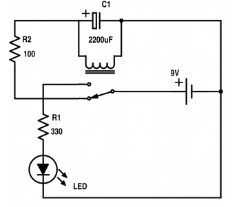
Circuit diagram
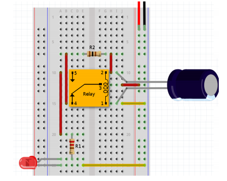
Breadboard layout
The breadboard diagram is shown below:
How it works
- At first when you connect the battery, current will run through R2 and C1 back to the battery.
- In the very beginning when the capacitor is without charge, almost all the current will flow through it instead of the relay-coil. But, as the capacitor is charing, more current will start to flow through the relay-coil instead.
- When enough current is running through the relay-coil, the electromagnet will pull the switch so it changes position.
- Now, since the capacitor has some energy built up, it will make the electromagnet keep pulling the switch even though the battery was disconnected from it. While the switch is in this position, current will flow from the battery to R1 and the LED and the LED will light up.
- When there is no more energy left in the capacitor, the electromagnet stops pulling and the switch goes back to its original position again.
- The cycle repeats itself!
Assembling
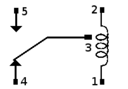
- You can use any 9V relay for this example, but note that the pin arrangement on a relay varies between relay types. On many relays, the pin arrangement is printed on top of the relay, so that you know which pin is which.
- You may need to lookup the pinout of the relay in the manufacturer’s data-sheet for the relay you are using.
- Note: Not all relays are fitted for easy use on a breadboard, so you might need to bend the legs a little bit to get it to fit into the breadboard.
- Mentors may provide some relays which has wires soldered to it as an alternative.
- Start by connecting the battery connector to the supply rail on the side. The red wire is the positive terminal, the black wire is the negative one.
- Next, place the relay on the breadboard. Then connect the resistor (R2) from pin 4 to pin 2 of the relay. Connect a wire from the positive supply rail to the relay input (pin 3) and from the negative supply rail to the relay coil (pin 1).
- Add the capacitor over the relay coil. The relay coil doesn’t have a positive or negative side, but this type of capacitor, polarized capacitor, does. So place the capacitor with the negative pin at the lower end (pin 1) since we have connected the negative battery terminal here.
- The negative pin of the capacitor is usually marked with a “-” (minus sign) or a zero
- Now, if you power up the circuit you should hear a clicking sound. If not, check your connections before proceeding. A smart thing to check is the voltage on the relay coil. If there is no voltage there, something is wrong.
- When you have gotten the clicking sound, it’s time to connect the resistor (R1) and the Light Emitting Diode (LED). Connect them from the second output of the relay (pin 5) and back to the negative battery terminal (as shown in the diagram above).
Troubleshooting
- It’s easy to make a mistake when connecting a circuit for the first time. A common mistake is to connect the LED the wrong way. Make sure your LED is connected the right way, with the long leg to the resistor and the short leg to the negative supply rail.
- Another common mistake is to connect the two output pins from the relay the other way around. Double check that you have this connection correctly connected.
- When you have checked that all your connections are okay, connect the battery. You should now hear a ticking of the relay and your LED should be flashing.
Further experiments
- The size of the capacitor and the resistor (R2) shown in the circuit diagram determines how fast the light blinks.
- If R2 is too large, the electromagnet never turns ON. If it’s too small, the electromagnet turns on so fast that you might not see the light turn OFF.