Blinking LED using 555 timer
2019-02-23 - Authored by: fionnc
Integrated Circuits
- As part of a coderdojo session we learned about integrated circuits (ICs) or
chips. You shouldn’t pour ketchup on these type ofchipsthough ;-) ! - We learned there are lots of different electronic microchips each one having a special purpose or function for different types of jobs.
- They sometimes look like caterpillars, the ones inside printed circuit boards can sometimes be tiny.
- Some chips have more legs than others some have 8 pins, others 16 and some have even more!
- If you could look inside the chips you’d see it contains a circuit itself - with resistors, capacitors, transistors..
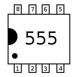
555 timer
- One
chipwe looked at is the555 timerchip. - The 555 timer is a type of integrated circuit
- 555 timer can be used as a timer and is used a lot.
- It gets the name from the three
5KΩ resistorsthat used inside the chip itself to generate voltages. - We learned to lookup the
datasheetassociated with the 555 to understand what the purpose of the chip is ( orspecifications) and better understand what each pin does. - The dot on the corner of the chip shows the position of pin #1
Components used
These are the components we used to make a 555 timer with 2 blinking LEDs
| Name | Quantity | Component |
|---|---|---|
| BAT1 | 1 | 9V Battery |
| R1, R2 | 2 | 330 Ω Resistor |
| LED1 | 1 | Red LED |
| LED2 | 1 | Green LED |
| IC1 | 1 | Timer |
| R3, R4 | 2 | 100 kΩ Resistor |
| C2 | 1 | 10 uF, 25 V Polarized Capacitor |
Breadboard diagram
Here is the breadboard diagram for the blinking LED project:
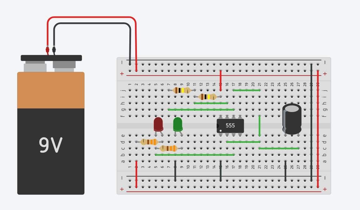
I prototyped the circuit in Tinkercad then afterwards built the circuit on a physical board.
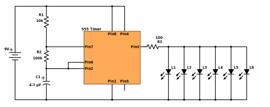
A fancier version (Mark 2)
Here is a circuit diagram of a 555 blinking LED circuit with even more LEDS! I tried to build this circuit in Tinkercad, but the circuit didn’t work for me. We double checked the connections, however, when testing some circuits in Tinkercad, it seems that Tinkercad doesn’t simulate the circuit very well. So, we tried to build it for real - I found this one tricky to build. It took a while, but it was fun to see it working in the end. Maybe you will have better luck to build in real life ?
What we learned
- We learned about microchips and how to use a 555 timer in a circuit to make an LED blink.
- We looked at a number of YouTube videos including Electronics - 555 Timer, A Microchip Project to help understand how the
555 timerworks - We also learned about Markdown and we used dillinger.io which can be used as a way to format this page.
- Content in
markdowncan be published to the CoderDojo Athlone Projects Website with the help of a mentor!